Detection response task
The DRT module runs a Red Scientific detection response task unit, plots reaction times as they arrive, and writes one row per stimulus with the reaction time the device measured.
The DRT product page describes the kit and the method.
- Reaction time
reaction_time_ms, measured on the device, 1 ms resolution- Miss
reaction_time_msis-1: no press before the next stimulus- Line up with other modules
record_time_mono- ISO 17488 hit window
- 100 to 2500 ms after onset. Applied by you in analysis, not by RSLogger
Getting started
- Connect the unitPlug the wired DRT into a USB port, or plug the XBee coordinator in for a wireless DRT.
- Enable the moduleCheck DRT in the Modules menu. RSLogger scans the serial ports and lists each unit in the Devices panel. Click the unit to connect it; its window opens and its indicator turns green. RSLogger reconnects it on the next start. For a wireless unit, click Rescan if it does not appear.
- Set the timingFile > Configure… in the DRT window. Upload ISO loads the ISO 17488 values.
- RecordStart a session and click Record. The device starts presenting stimuli and the window plots each response.
Stimulus types
The kit has three stimuli. All three plug into the same controller and the module does not need to know which is fitted.
| Type | Description | Typical use |
|---|---|---|
| TDRTTactile | A vibration motor worn on the shoulder or collarbone. Places no demand on vision. | Studies of displays and touchscreens, where a visual stimulus would compete with the task under test. |
| HDRTHead-mounted | A red LED on a headband in the peripheral visual field. It moves with the head, so its visual angle stays constant. | Tasks where the head moves and the stimulus must stay in the same place relative to the eyes. |
| RDRTRemote | An LED fixed in the cabin, on the dashboard or A-pillar. Earlier literature calls this the peripheral detection task. | In-vehicle studies with a fixed reference point in the cabin. |
The DRT window
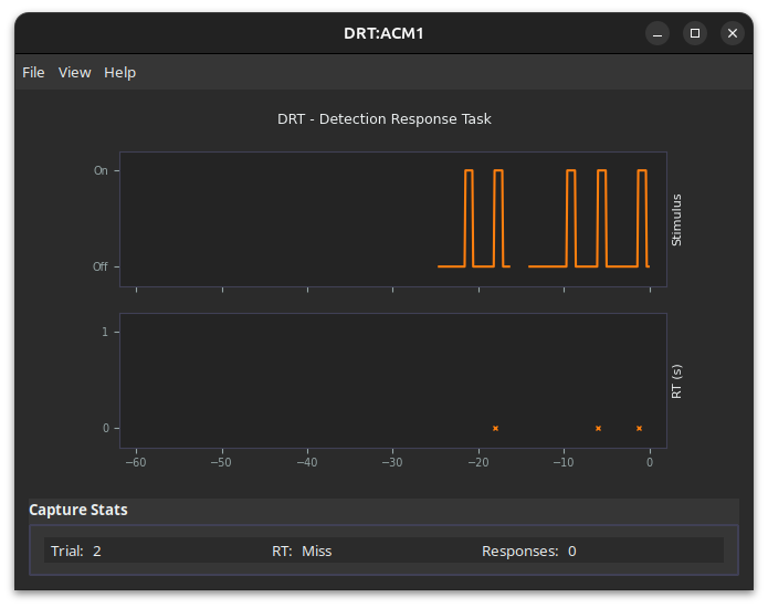
The upper plot shows the stimulus state over the last 60 seconds and the lower plot marks each reaction time. Capture Stats below them show the stimulus count, the last reaction time or Miss, the number of button presses, and the battery level of a wireless unit. The menus are File (Configure…), View (Stimulus: ON and Stimulus: OFF, to test the stimulus by hand) and Help.
Configuration
File > Configure… opens the Runtime Parameters dialog. The values live on the device and survive power cycles.
| Parameter | ISO value | Meaning |
|---|---|---|
| Lower ISI (ms) | 3000 | Shortest interval from one stimulus onset to the next. |
| Upper ISI (ms) | 5000 | Longest interval. The device draws each interval at random between the two. |
| Stimulus Duration (ms) | 1000 | How long the stimulus stays on if there is no response. A response turns it off at once. |
| Stimulus Intensity (%) | 100 | LED brightness or motor drive. |
Upload ISO writes the four ISO 17488 values to the device. Upload Custom writes whatever is in the fields.
What is logged
The module writes one CSV per unit for the whole session, in the DRT folder, and appends one row for each stimulus.
{session_dir}/DRT/{token}_DRT_dev_ttyacm0.csv| Column | Description |
|---|---|
reaction_time_ms | Onset to first press, in milliseconds, measured on the device. -1 when there was no press before the next stimulus. |
responses | Button presses between this stimulus and the next. |
device_time_offset | Stimulus onset in milliseconds since the device started the experiment, on the device’s clock. |
trial | The device’s stimulus count. It restarts at 1 each time you press Record, so tell trials apart by label or by the session’s control file. |
record_time_mono, record_time_unix | Host time when the result message arrived. Use for lining up with other modules. |
stim_type | Wired unit only. 1 for the standard stimulus. Standard firmware never writes 2. |
battery_percent | Wireless unit only. |
The data output reference lists all eleven columns in order.
A row with -1 is a stimulus the participant did not answer. ISO 17488 treats hit rate and reaction time as two separate measures, and both rise and fall with cognitive load, so keep the miss rows and report both.
How the reaction time is measured
The device measures the reaction time itself. Its firmware notes the time it switches the stimulus on and the time it sees the first button press, and reports the difference. Host latency does not enter into it. The two units do this differently, and the difference is worth knowing when you compare them.
| Wired DRT | Wireless DRT | |
|---|---|---|
| Clock | Millisecond timer | Microsecond timer, rounded to 1 ms |
| Press detection | Polled through a switch debounce that reports a press once the contact has been steady for 5 ms | Hardware interrupt on the contact’s first edge, then a lockout against bounce |
| Effect on the value | Every reaction time is reported about 5 ms late. The offset is the same on every trial, so it cancels in comparisons between conditions on the same unit | No debounce delay |
| Connection | USB serial | XBee radio to a USB coordinator |
| Power | USB | Battery, level in battery_percent |
| Several units at once | Each unit on its own USB port gets its own window | Several units on one coordinator, each with its own window |
These statements come from reading the firmware. Neither unit’s timing has been characterized on a bench, and no accuracy figure is claimed.
Applying the ISO 17488 window
ISO 17488 counts a response as a hit when it comes 100 to 2500 ms after onset. A response inside 100 ms is premature, and the standard excludes that stimulus from the hit rate. A response after 2500 ms does not count. RSLogger records the raw reaction time and leaves this classification to you:
import pandas as pd

drt = pd.read_csv("20260318_143022_DRT_dev_ttyacm0.csv")
rt = drt["reaction_time_ms"]

premature = rt.between(0, 99)
hit = rt.between(100, 2500)
scored = ~premature                       # ISO excludes premature stimuli from the hit rate

hit_rate = hit[scored].mean()
mean_rt = rt[hit].mean()                  # reaction time is reported over hits only
A row with -1 is a miss. A row with a reaction time above 2500 ms is also a miss under the standard, although the device recorded a press.
Troubleshooting
The unit is not detected
Confirm that it appears as a serial port: a COM port on Windows, /dev/ttyACM* on Linux, /dev/tty.* on macOS. If no port appears, try another cable. Some USB cables carry power only.
On Linux, your user must be in the dialout group to open the port. Log out and in after adding it.
No stimulus appears
Check that Stimulus Intensity is above 0 and Stimulus Duration is not 0. Check that the stimulus is plugged into the stimulus port on the controller. Stimuli are presented only while a trial is recording. View > Stimulus: ON turns the stimulus on by hand for a test.
Every stimulus is a miss
The response switch is not registering. Check that it is plugged into the response port and that Responses in Capture Stats counts up when you press it.
A wireless unit drops out
Keep the coordinator in range of the unit and away from large metal surfaces. Check battery_percent in the last rows written. Click Rescan in the Devices panel after the unit comes back.